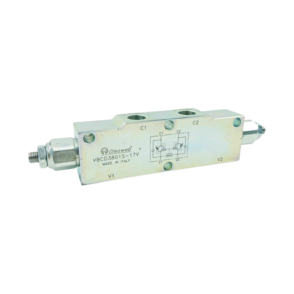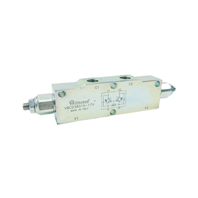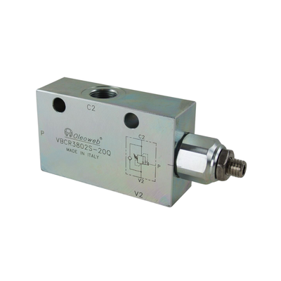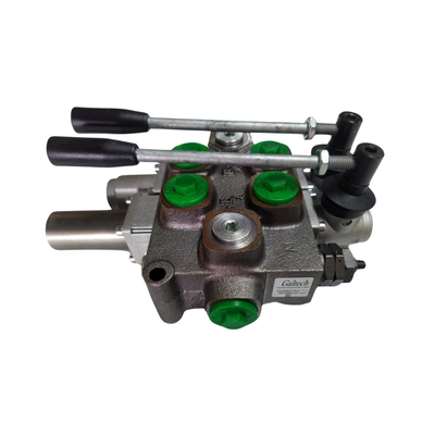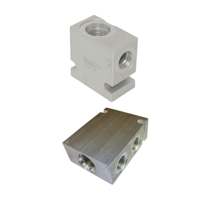
Dual Counter Balance Valve 3/4 BSPP ports 120 l/m 60 - 350 bar
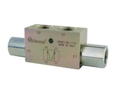
Dual Counter Balance Valve with internal Vent, flows up to 120 Lt/min, 3/4 BSPP Ports, pressure range 60 to 350 bar.
Available in Various Pilot Ratios 3:1, 4.25:1, and 8:1
Dual Counter Balance, are also called Load Hold or Craning valves with open centers and 3/4" BSPP Ports.
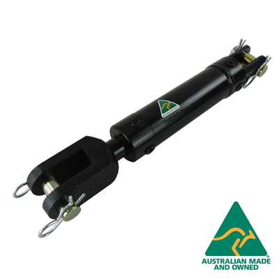
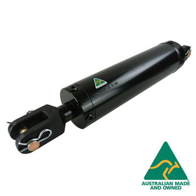
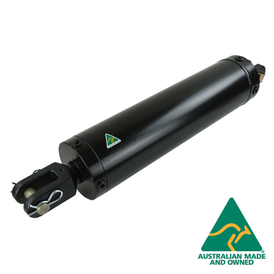
These are widely used on cylinders used as stabiliser legs, crane cylinders, winch motors and other hydraulic uses where it is essential a function does not drop if hydraulic power is lost ie. broken hose or fitting.
These valves are a mandatory safety item for many hydraulic applications.
Adding a counterbalance valve controls motion and provides protection against hose or tube failure. In this circuit, moving the directional control valve to the left causes the cylinder to extend, raising the load with free flow going through the check valve portion of the counterbalance valve.
When the directional control valve is centered, the counterbalance valve will prevent leakage and lock the load in position.
Moving the directional control valve to the right sends flow/pressure to the rod end of the cylinder. This pressure also acts to pilot open the counterbalance valve and allows the load to be lowered.
Counterbalance valves will positively hold a pressurized load and will control the motion of the load based on application of a pressure signal to the pilot port. Single inline pilot check valves are also available.
Adding or installing a Counterbalance Craning or Load hold valve to an existing hydraulic circuit proceed as follows.
1. The counter balance valve has 4 ports marked as V1, V2, C1, C2.
2. V1 and V2 are connected to the oil supply flowing To and From the flow control valve (usually labeled A and B ports on the flow control valve)
3. C1 and C2 should be connected directly to the cylinder ports or winch motor ports preferably with solid steel pipes and or steel adaptors.
4. Try and avoid using flexible hose connections on the C1 and C2 connections as these may be rejected during some safety inspections.
This valve controls a moving load in BOTH directions, preventing it from moving ahead of the pump & locks the load in any position on C1 or C2. You can adjust the counterbalance valves with an Allen key to speed or slow the cylinder travel to equal out two cylinder speeds. 1 full turn equals aprox. 1000 PSI per turn.
These are quality items made in Italy.
### Pressure Rating = 60-350bar (880-5100 PSI)
Flow = 120 LPM
Ratio = 6:2:1
Size = 3/4" Full Bore
Ports = 4 x 3/4" BSPP Female.
Materials of Construction
Body = Zinc Plated Steel
Seals = Viton.
Some additional guidelines for counterbalance valve applications:
- Specify the counterbalance valve relief setting high enough to stop any motion (flow) at the maximum expected actuator pressure. Generally it is recommended to use a setting of 1.3 multiplied by the maximum load pressure.
- Use low pilot ratios (3:1 and 4.5:1) for applications where loads may vary widely. Low pilot ratios require higher pilot pressure and are less efficient but provide stable, precise control for varying loads.
- Use high pilot ratios (8:1 and 10:1) for applications where loads are relatively constant. High pilot ratio valves require lower pilot pressure, have faster response, and are more efficient, but lack stability and precision in response to varying loads.
- Do not oversize counterbalance valves. There is no pressure drop operating limit for counterbalance valves and in fact some pressure drop is required to maintain valve operation.
- Locate counterbalance valves at or near the actuator to provide maximum load holding protection in the event of hydraulic line failure.
- Do not use counterbalance valves with closed-center directional control valves. Pressure trapped between the directional control valve and the actuator can pilot the counterbalance valve open and result in undesired load motion.
Do not use counterbalance valves with tandem-center directional control valves.
Hydraulic.Online
IMPROPER SELECTION, INSTALLATION, IMPLEMENTATION AND/OR OPERATION BY ANYONE OTHER THAN PERSONS WITH APPROPRIATE TECHNICAL AND MECHANICAL TRAINING CAN RESULT IN DAMAGE TO EQUIPMENT OR PROPERTY, SERIOUS PERSONAL INJURY OR DEATH. PROPER PRECAUTIONS AND SAFETY PROCEDURES SHOULD BE IMPLEMENTED PRIOR TO INSTALLATION AND OPERATION OF EQUIPMENT.
MM 19/09/2024 $ abc title SEO

