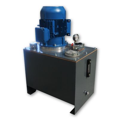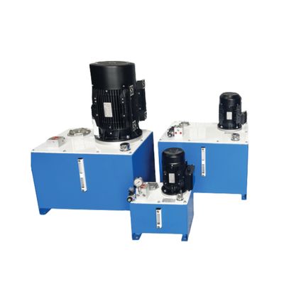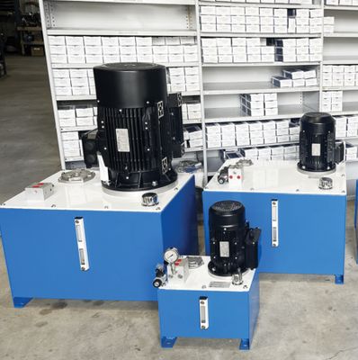
Industrial Hydraulic Power Units
Generally, Hydraulics is governed by three interrelated parameters:
- Flow in Lt/Min
- Pressure in Bar or psi
- Power in kW or HP
These parameters are interconnected and influence each other within a hydraulic system.
- Flow represents the volume of fluid moving through the system per unit time.
- Pressure is the force exerted by the fluid per unit area.
- Power is the rate at which work is done, which in a hydraulic system is directly related to both flow and pressure.
Example 1: Increasing Flow at Constant Pressure
Case: Let's consider a system operating at a constant pressure of 50 bar.
Results from Observations: As we increase the flow from 30 L/min to 100 L/min, the power requirement significantly increases from 2.9 kW to 9.6 kW.
Explanation:
- Increasing flow at constant pressure demands more energy to move the fluid volume.
- This is because the system needs to overcome the resistance to flow (like viscosity) at a higher rate.
Example 2: Increasing Pressure at Constant Flow
Case: Let's analyse a system operating at a constant flow of 100 L/min.
Results from Observations: As we increase the pressure from 1 bar to 100 bar, the power requirement dramatically increases from 0.2 kW to 19.2 kW.
Explanation:
- Increasing pressure at constant flow requires significantly more energy.
- This is because overcoming higher resistance (due to increased pressure) requires more force, and thus, more power.
Key points to Consider
Flow and Pressure are Directly Proportional to Power:
Increasing either flow or pressure (or both) will result in a substantial increase in power requirements.
System Design Considerations:
- Hydraulic Technicians and Engineers must carefully balance flow, pressure, and power requirements to optimise system efficiency and minimise energy consumption.
- For example, if high flow is required, reducing pressure where possible can help to minimise power consumption.
Important Notes:
The provided data may represent a specific type of hydraulic system or component application.
The actual relationships between flow, pressure, and power can vary depending on factors such as fluid viscosity, system complexity, and component design.
The Chart below is a great cross reference tool to quickly check the relationship between Flow, Pressure and Power requirements.
Use the Chart below to help you calculate the Electric Motor power Requirements To Drive a Hydraulic Pump to achieve your desired Flow and Pressure.
The chart below is based on the formula
kW = Lt/min x Bar
612 x Efficiency
This chart assumes a pump efficiency of 85% (as Pressure increases efficiency decreases)
| LPM | 30 BAR | 40 BAR | 50 BAR | 60 BAR | 70 BAR | 80 BAR | 90 BAR | 100 BAR | 125 BAR | 150 BAR | 175 BAR | 200 BAR |
| 1 | 0.1 | 0.1 | 0.1 | 0.1 | 0.1 | 0.2 | 0.2 | 0.2 | 0.2 | 0.3 | 0.3 | 0.4 |
| 2 | 0.1 | 0.2 | 0.2 | 0.2 | 0.3 | 0.3 | 0.4 | 0.4 | 0.5 | 0.6 | 0.7 | 0.8 |
| 3 | 0.2 | 0.2 | 0.3 | 0.3 | 0.4 | 0.5 | 0.5 | 0.6 | 0.7 | 0.9 | 1 | 1.2 |
| 4 | 0.2 | 0.3 | 0.4 | 0.5 | 0.5 | 0.6 | 0.7 | 0.8 | 1 | 1.2 | 1.3 | 1.5 |
| 5 | 0.3 | 0.4 | 0.5 | 0.6 | 0.7 | 0.8 | 0.9 | 1 | 1.2 | 1.4 | 1.7 | 1.9 |
| 6 | 0.3 | 0.5 | 0.6 | 0.7 | 0.8 | 0.9 | 1 | 1.2 | 1.4 | 1.7 | 2 | 2.3 |
| 7 | 0.4 | 0.5 | 0.7 | 0.8 | 0.9 | 1.1 | 1.2 | 1.3 | 1.7 | 2 | 2.4 | 2.7 |
| 8 | 0.5 | 0.6 | 0.8 | 0.9 | 1.1 | 1.2 | 1.4 | 1.5 | 1.9 | 2.3 | 2.7 | 3.1 |
| 9 | 0.5 | 0.7 | 0.9 | 1 | 1.2 | 1.4 | 1.6 | 1.7 | 2.2 | 2.6 | 3 | 3.5 |
| 10 | 0.6 | 0.8 | 1 | 1.2 | 1.3 | 1.5 | 1.7 | 1.9 | 2.4 | 2.9 | 3.4 | 3.8 |
| 11 | 0.6 | 0.8 | 1.1 | 1.3 | 1.5 | 1.7 | 1.9 | 2.1 | 2.6 | 3.2 | 3.7 | 4.2 |
| 12 | 0.7 | 0.9 | 1.2 | 1.4 | 1.6 | 1.8 | 2.1 | 2.3 | 2.9 | 3.5 | 4 | 4.6 |
| 13 | 0.7 | 1 | 1.2 | 1.5 | 1.7 | 2 | 2.2 | 2.5 | 3.1 | 3.7 | 4.4 | 5 |
| 14 | 0.8 | 1.1 | 1.3 | 1.6 | 1.9 | 2.2 | 2.4 | 2.7 | 3.4 | 4 | 4.7 | 5.4 |
| 15 | 0.9 | 1.2 | 1.4 | 1.7 | 2 | 2.3 | 2.6 | 2.9 | 3.6 | 4.3 | 5 | 5.8 |
| 20 | 1.2 | 1.5 | 1.9 | 2.3 | 2.7 | 3.1 | 3.5 | 3.8 | 4.8 | 5.8 | 6.7 | 7.7 |
| 25 | 1.4 | 1.9 | 2.4 | 2.9 | 3.4 | 3.8 | 4.3 | 4.8 | 6 | 7.2 | 8.4 | 9.6 |
| 30 | 1.7 | 2.3 | 2.9 | 3.5 | 4 | 4.6 | 5.2 | 5.8 | 7.2 | 8.7 | 10.1 | 11.5 |
| 35 | 2 | 2.7 | 3.4 | 4 | 4.7 | 5.4 | 6.1 | 6.7 | 8.4 | 10.1 | 11.8 | 13.5 |
| 40 | 2.3 | 3.1 | 3.8 | 4.6 | 5.4 | 6.2 | 7 | 7.7 | 9.6 | 11.5 | 13.5 | 15.4 |
| 50 | 2.9 | 3.8 | 4.8 | 5.8 | 6.7 | 7.7 | 8.7 | 9.6 | 12 | 14.4 | 16.8 | 19.2 |
| 60 | 3.5 | 4.6 | 5.8 | 6.9 | 8.1 | 9.2 | 10.4 | 11.5 | 14.4 | 17.3 | 20.2 | 23.1 |
| 70 | 4 | 5.4 | 6.7 | 8.1 | 9.4 | 10.8 | 12.1 | 13.5 | 16.8 | 20.2 | 23.5 | 26.9 |
| 80 | 4.6 | 6.2 | 7.7 | 9.2 | 10.8 | 12.3 | 13.8 | 15.4 | 19.2 | 23.1 | 26.9 | 30.8 |
| 90 | 5.2 | 6.9 | 8.7 | 10.4 | 12.1 | 13.8 | 15.6 | 17.3 | 21.6 | 26 | 30.3 | 34.6 |
| 100 | 5.8 | 7.7 | 9.6 | 11.5 | 13.5 | 15.4 | 17.3 | 19.2 | 24 | 28.8 | 33.6 | 38.4 |
MM 28/01/2025 all New


