Hydraulic Inline Flow Meter & Pressure Test Kit 120 Lt/Min 420 bar
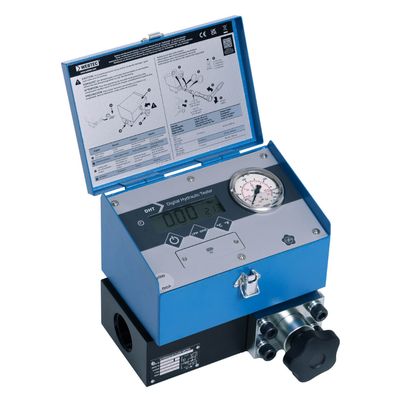
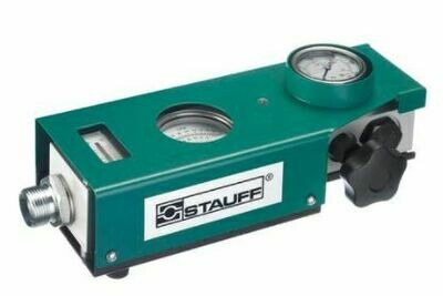
STAUFF Inline Hydraulic Flow & Pressure Test Kit | 120 Lt/min | 6,000 PSI (420 Bar)
Diagnose hydraulic circuit failures with precision using the industry-standard Stauff Inline Flow Meter kit. Assembled and tested in Australia by veteran hydraulic fitters, this kit is the definitive solution for performance testing and troubleshooting mobile and industrial hydraulic systems.
Key Features & Capabilities:
- Flow Range: Up to 120 Lt/min (30 US GPM).
- Pressure Rating: Rated up to 420 Bar (6,000 PSI).
- Accuracy: ± 4% of full scale.
- Flow Configuration: Choose between Standard One-Way Flow or the upgraded Bi-Directional Reversible Flow model (ideal for Hydrostatic Transmissions and Reversible Piston Pumps).
- Thermal Monitoring: Built-in thermometer for real-time oil temperature tracking.
- No Power Required: Fully mechanical operation—no batteries or electrical connection needed.
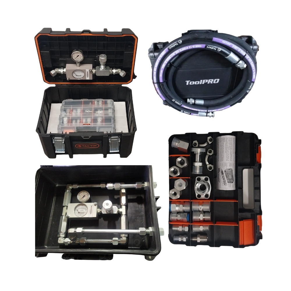
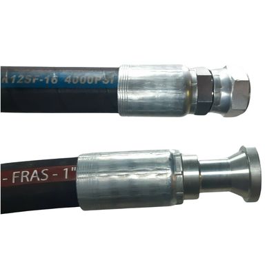
Comprehensive Adaptor & Hose Options: This kit is supplied in a heavy-duty carry case with or without the option of two (2)
2-metre long 3/4" bore test hoses. Select your required pressure rating:
- No Test Hoses
- Optional: 2 x 2 m long SAE 100R2 (3,200 PSI)
- Optional: 2 x 2 m long SAE 100R19 (4,000 PSI)
- Optional: 2 x 2 m long SAE 100R15 (6,000 PSI)
Included Adaptor Set (18 Pieces):
- BSP Threads: 1/4" to 3/4"
- JIC Threads: 9/16" to 1-1/16"
- ORFS Threads: 9/16" to 1-3/16"
- SAE Code 61: 3/4" Flange
Diagnostic Applications: Designed for equipment up to 12 tonnes, including tractors, skid steers, excavators, forklifts, and concrete agitators. It allows for the individual testing of pumps, directional control valves, relief valves, and cylinders.
Operational Procedure for Pump Testing:
- Install: Plumb the meter as close as possible to the pump's pressure port.
- Baseline: Start the pump and record the Lt/min at zero pressure and current temperature.
- Load Simulation: Gradually close the flow control valve to induce resistance.
- Data Recording: Log flow readings at 500 PSI intervals up to the manufacturer’s maximum rated pressure.
- Evaluation: Compare results against factory specs. A drop of more than 20% in flow compared to the baseline typically indicates significant internal wear.
Dispatch Note: Please allow 4 - 8 business days for professional assembly and testing prior to dispatch.
Technician’s Advice
The Bi-Directional upgrade is exceptional value for money. It utilizes four high-quality inline check valves to allow flow measurement in both directions without replumbing.
This is essential for testing hydrostatic drives on skid steers or tilt trays where you need to see if the pump or motor is failing in one specific direction.
Remember: always perform your final test at normal operating temperature (50°C - 60°C), as thin, hot oil will reveal internal leakage that might stay hidden when the machine is cold.
Example of a Hydraulic Component Performance Test Sheet
Project: ____________________ | Date: ____ / ____ / 2026
Component (Pump/Motor): ____________________
Rated Flow (from Manual): __________ Lpm @ __________ RPM
1. Preparation Checklist
- [ ] Safety glasses and gloves on.
- [ ] Needle valve fully open (Turn anticlockwise) before starting.
- [ ] Return line connected securely back to the tank.
- [ ] Flow direction matches the arrow on the Flow Meter.
- [ ] Engine/Motor set to standard operating RPM.
Please note as Load and pressure Increases it is important to maintain a steady and consistent RPM.
Please See Flow Pressure Testing Chart on Next Page
3. Analysis (The "20% Rule")
- Formula: $Baseline\ Flow \times 0.8 = Minimum\ Acceptable\ Flow$
- Example: If your pump flows 70 Lpm at 0 PSI, it should still flow at least 56 Lpm at full working pressure.
- Verdict: If your "High Pressure" flow reading is more than 20% lower than your "0 PSI" reading, internal wear (slippage) is present.
Technician’s Advice
Don't forget to monitor your oil temperature during the test. As oil gets hotter, it gets thinner (lower viscosity), which will increase "slippage" in a worn pump.
If your machine works fine for the first 10 minutes but loses power as it warms up, perform this flow test once the oil has reached its normal operating temperature (usually 50°C to 60°C).
2. Flow / Pressure Test Results
Use the table below to record the flow rate as you increase the resistance (pressure) using the needle valve.
|
Pressure (PSI) |
Pressure (Bar) |
Indicated Flow (Lt/min) |
Notes |
|
0 PSI |
0 Bar |
Base Flow (No Load) |
|
|
500 PSI |
35 Bar |
||
|
1,000 PSI |
70 Bar |
||
|
1,500 PSI |
100 Bar |
||
|
2,000 PSI |
140 Bar |
||
|
2,500 PSI |
175 Bar |
||
|
3,000 PSI |
210 Bar |
||
|
3,500 PSI |
240 Bar |
MM 03/02/2026 ABC Alt text
BI-DIR PO-36842, 36841, 36832
